*English version
by Eric Schurmann, November 2008*
Machine from patent of 1841 (modified) |
Prototype not described |
|
|
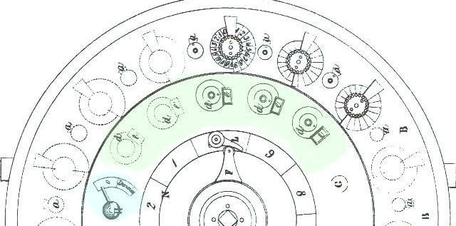
A) Outside circle/ The totaliser
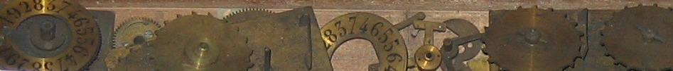
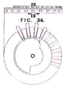
The totaliser is composed of a series of 9 dials, each with a series of numbers (0-9/9-0) as described in the 8th attempt. The discs are pierced with 20 holes. The right half is used for addition and the left for subtraction. The series of numbers are placed semi-cicularly. (They are red for subtraction).
The machine does not have a reseting mechanism. The carry mechanism is of the type of the fourth attempt. The double cam is not yet present on the latest adders which would seem to indicate that Roth was working simultaneously on the construction of his multiplier and the technical development of his adders. The multiplier, much more complex, contains certain technical choices which have remained fixed in time. The result of the cohabitation of different innovations.
Outside circle/Totaliser |
|
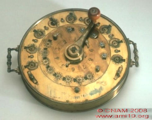
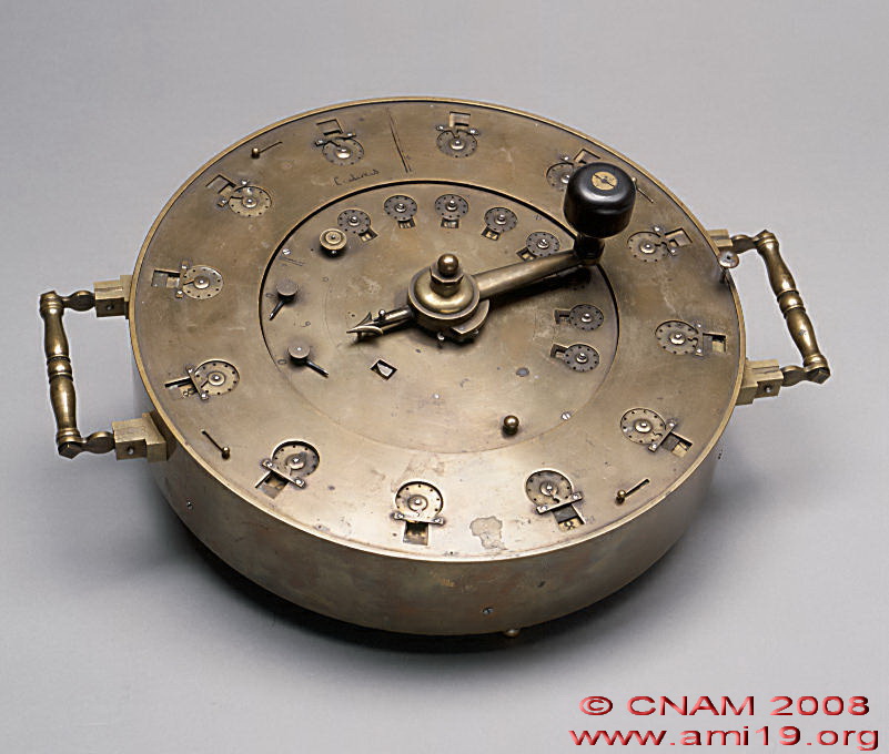
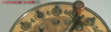
Detail of the machine kept at the CNAM |
|
In short, we have here a series of twenty toothed wheels on which two series of numbers are engraved in double (complementary numbering). As each tooth corresponds to a unit, it's not one but two little rods, fixed under the wheel, that are going to act, at each half-turn, on a lever which will move the following wheel forward one notch.
Since the machine is round, the dials are positioned on a curved line (Note: Roth pointed out that he could have made a straight machine without any problem). Between each dial, and unlike the simple adders, turn counters (quotient) have been added (8 counters).
Under each dial, a small gear wheel engages with an eccentric pinion which moves the turn counter (quotient).
B) Mobile middle section
1) The registers
It is composed of 5 registers and a button to change between addition and subtraction. Each register is composed of a series of numbers engraved on the plate, numbered from 0 to 9, a central disc pierced by a single hole and a window showing the figures on the dial. When the exterior plate is removed, a large 100-toothed wheel (k) can be seen with five smaller wheels on the same axle as the registers.
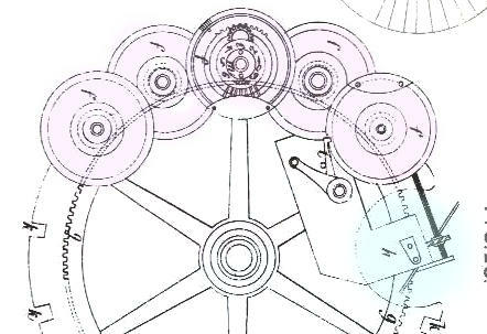
2) The development wheels
All Roth's genius resides in these 5 wheels, called development wheels.
Developpement wheels |
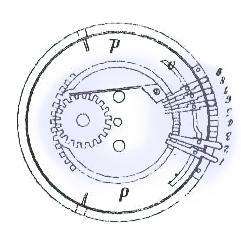
Mechanism with a variable number of teeth
|
|
|
|
System with variable number of teeth
I prefer to let Roth speak here:
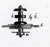
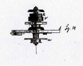
It's a "copper disc of which one fifth has nine grooves carved into its thickness.The grooves contain nine movable bolts which, when pushed towards the exterior, create as many teeth but which, when retracted into the grooves leave the edge of the disc perfectly smooth. If one of the bolts is moved out of its groove, the disc has one tooth; it has 2 if two bolts are moved out; nine if all the bolts are out of their grooves. On the other hand, it has none if none of the bolts is out of its groove. Each bolt has a pin in the middle which is acted on by a small inclined plane cut into a moving plate which covers the disc and its grooves. It is thanks to this inclined plane that the bolts are moved out of their grooves and returned.
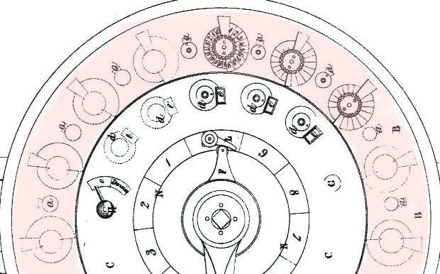
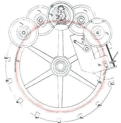
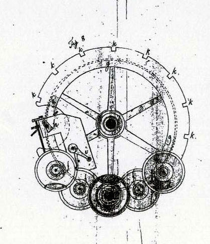
Imagine now that the five development wheels are placed in a circular line on the lower part of the mobile plate, and that the big central wheel has 100 teeth which engage with the twenty toothed pinions of the lower part of the development wheels. Imagine the big wheel divided into ten equal parts and it is easy to see that, while it makes one tenth of a turn, the development wheels make a full turn around their axles".
Roth precedes Odhner's variable toothed wheel by more than 40 years.
If we now put the development wheels in contact with the adder mechanism of the exterior circle (described above) the feat is done!
2) The multiplier
Large hundred toothed wheel |
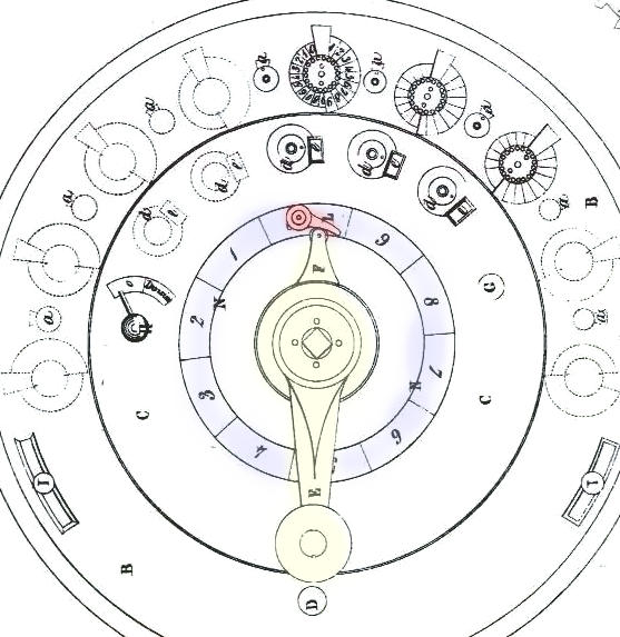
Circular dial, moving pointer and stop hookt |
|
|
The big central wheel had one hundred teeth. Imagine that each development wheel has one protruding tooth (i.e. the value 11111 on the registers) If the big wheel makes a tenth of a turn, the development wheels are going to add one unit to each of the totalisers and, therefore, mark 11111. If it makes 4 tenths of a turn, the totalisers will show 44444.
The operator indicates the value of the multiplier on a circular dial with a moving pointer placed on the same axis as the crank. When the value is reached, the pointer comes up against a stop hook. The crank never makes a complete turn; a ratchet always makes it return to its starting position.
3) Movement of the carriage
Unlike the Thomas arithmometer, the central section, where the registers are, is the moving part. Quite simply, one releases it by pressing a button. Then one only has to place the first development wheel on the right in front of the units dial of the outer circle to begin the operation.
Note by Michel Bardel
"40 years before Odhner but long after Poléni!!!
On the other hand, this machine is to Poléni's variable toothed wheel as the CURTA is to Leibnitz' cylinder. A single central wheel which drives the mechanisms around its rim" MB
Example.
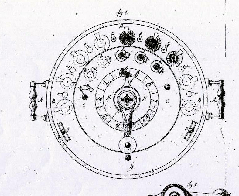
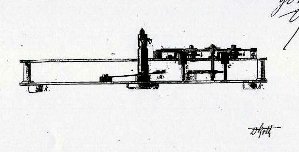
"26546 to be multiplied by 27. We begin by marking the figures 26546 on the five development wheels in the central part fig.1 ddddd so that they appear in the windows eeeee. The first wheel will have two bolts jutting out or two teeth, the second six, the third five, the fourth four and the fifth six.
In the middle of the moving part is a crank E, fig.1, which moves the big central wheel g, fig.8, which engages with the pinions of the development wheels k, fig.11 & 14. In the middle of the crank there is a ratchet wheel r carved in [ten ?] and fixed on the pipe of the big central wheel with its ratchet fixed on the crank in such a way as to permit only movement from right to left. If one turns it in the opposite direction, it no longer turns alone but drives with it the big centre wheel g, thanks to its ratchet s.
There is a hand on the crank which indicates on the circular dial, divided into ten parts numbered 0-9, how many tenths the centre wheel turns and, therefore, how many turns the development wheels make.
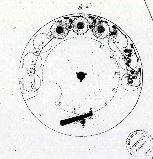
One must also remember that the lower plate of the moving section contains several grooves kkk fig.3 & 8, which hold the release M, fig.3. By means of the button D, fig. 1, 3 & 4, one lowers this release and, there being no further obstacle to movement, one places the first development wheel on the right in front of the units of the outer circle.
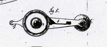
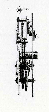
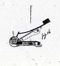
To carry out the proposed multiplication, one places the hand on the figure 2 and turns the crank until this hand arrives at 0. One then pushes the hook L, fig.5 & 10, which, via a stop, fig 16, fig 8, prevents the development wheels from turning any further. One has then multiplied by two and the upper windows of the addition will show the figure 53092.
Once this first result is obtained. one pushes the release button D, fig.1, which releases the central section and, by means of the driver button g, fig.1, turns this centre section from left to right so that the units of the amount to be multiplied shown on the development wheels are in front of the tens of the figure 53092.
One places the crank on the figure 7 and turns it until it reaches zero where it will, once again, be stopped.
The multiplicand will thereby be multiplied by 70 and the product of this multiplication will be added at the same time to the product of the multiplication by 2.
One will then see in the addition windows, the figure 1911312. One again moves the centre section, advancing it by one tenth, one puts the hand on 2 and, proceeding as before, one obtains the product of the multiplication by 200 added to the product of the multiplication by 72, One will find in the addition windows the total product 7220512"
To divide, one proceeds as follows:
To divide 7220512 by 26546.
One sets the divisor 26546 on the development wheels, as for the multiplication, and the dividend on the lower series of numbers on the wheels on the outer circle designed for subtractions which appear on closing the upper addition figures with the buttons tt, fig.1.
One places the middle moving plate in such a way that the first figure from the left is placed opposite the the first figure of the dividend. One then operates exactly as for the multiplication except that, instead of moving the central plate forward, one moves it back, always by one figure from left to right.
The result of the operation, i.e. the number of times that 26546 will have been subtracted from 7220512, will be given by the quotient 272 which will appear in the special windows aaaa, fig. 1.
To indicate how many times a figure has been subtracted from another, in other words the quotient, there is a particular mechanism in the machine which remains at rest throughout all the other operations and which only comes into play for division..
Here's how:
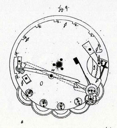
H, in fig.1, is a button which drives a hand. When this hand is in front of the inscription t [o?], the mechanism is at rest; it works when the hand indicates division.
This button H moves a lever u, fig.9, on the lower face of the lower plate of the central moving section.
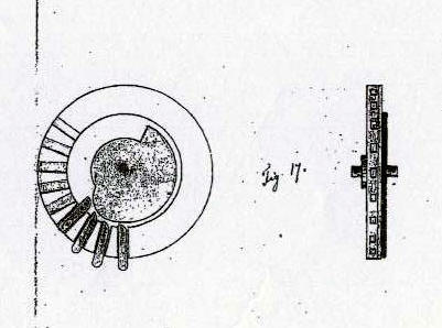
When the hand indicates division, the lever pushes outside the circumference of the circle, fig.9, a wheel x which engages with a pinion on the first development wheel v, fig.14, and which holds a pin y which counts, on the quotient wheels, fig.17, the number of turns made by the development wheels which constitutes the quotient.
*English version
by Eric Schurmann, November 2008*
|