*English version
by Eric Schurmann, November 2008*
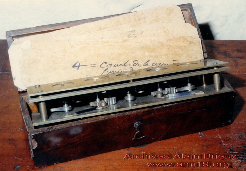
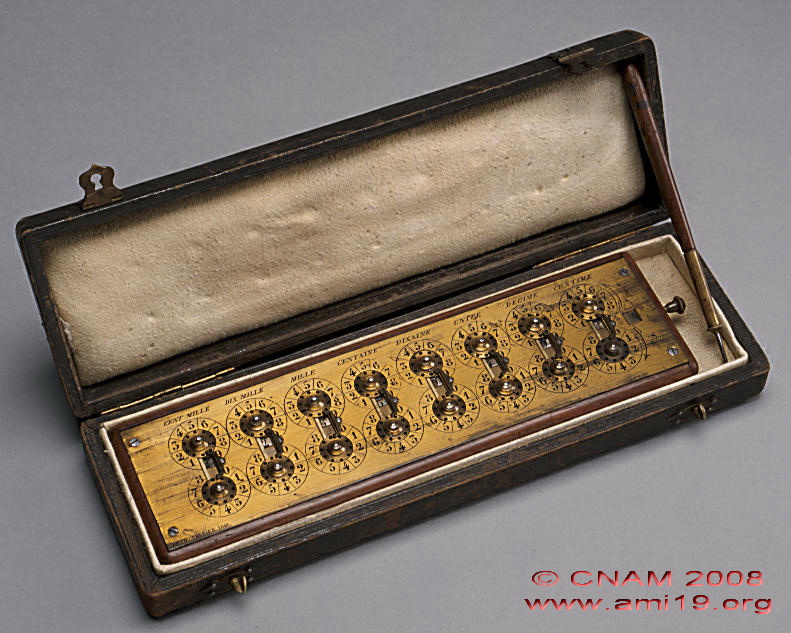
This machine seems to be Roth's first prototype. The mechanism is basic: under each dial (5 in all) is a single tooth which engages with an intermediate toothed wheel. This latter will transmit the carry to the next higher order of decimals. The machine is housed in a beautiful mahogany box which also contains a series of bound and annotated sheets. It comes from the old collection of Malassis who was a famous collector of calculating machines in the 1920's. Today, it is in the IBM collection in New York.
The Brunswick Museum has a replica which was made by Mr Trinks at the beginning of the last century. It is highly likely that Mr Trinks met Malassis at the calculating machines exhibition which took place in the premises of the Société d'Encouragement pour l'Industrie Nationale in 1920. Moreover, the archives of the Brunswick Museum confirm it.
|
|
Roth's original model (
1839-40 ?) |
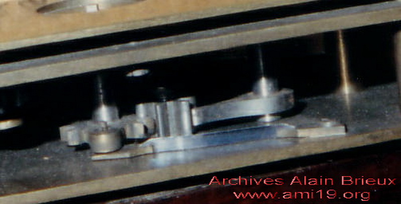
Detail of the single tooth mechanism |
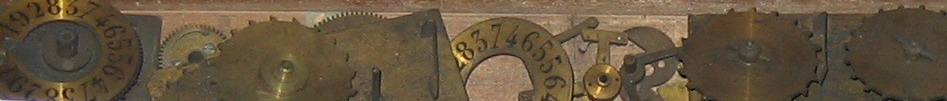
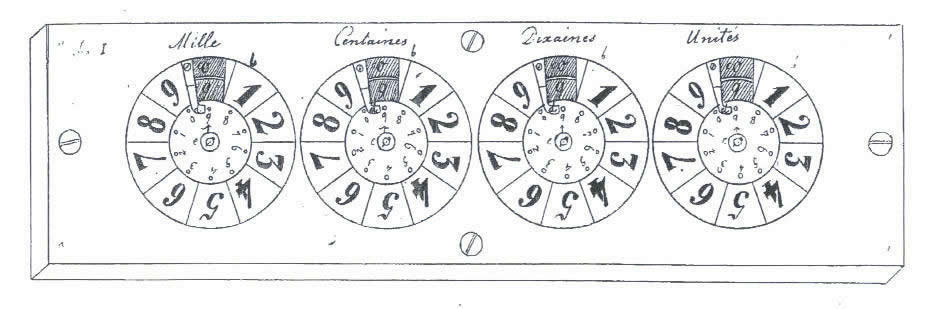
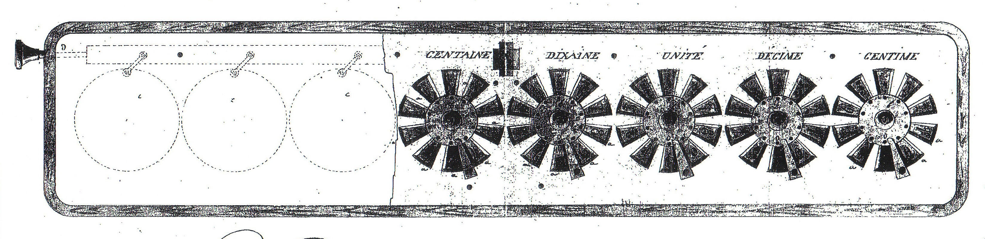
On the fixed plate, there are engraved circles numbered from 1 to 9 (here there are 4 circles). In the tens place (or zeroes) windows have been cut out to show the dials underneath. Central discs. each pierced with ten equidistant holes numbered from 0 to 9 are fixed on the dials. On each dial, one can see two series of numbers from 0 to 9 and inverted (complementary numbering).
Little hooks on the left of the windows extend to the central discs and act as stops when the operator introduces his stylus.
|
|
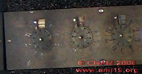
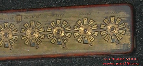
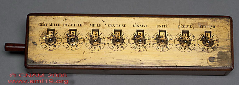
Detail of the prototype R1 of 1840
Source : CNAM |
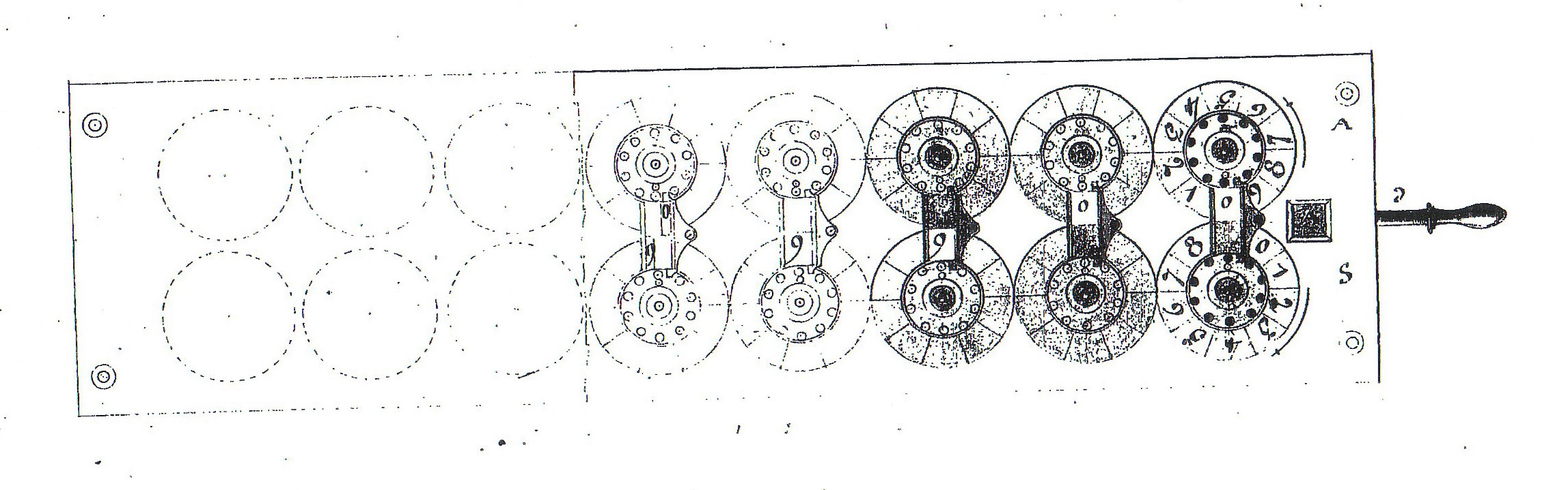
Model R1 with 4 digits
Source : Patents |
Dr Roth thought up 4 different systems for the carry !!
Here are the details
|
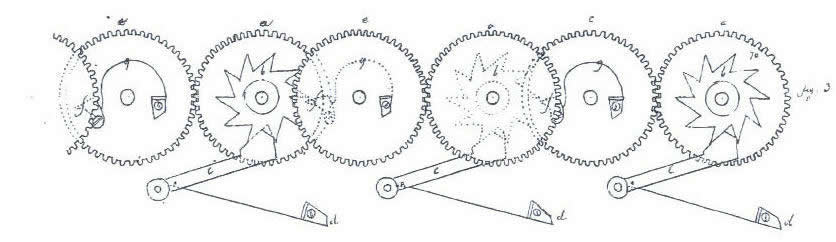
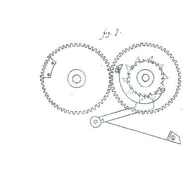
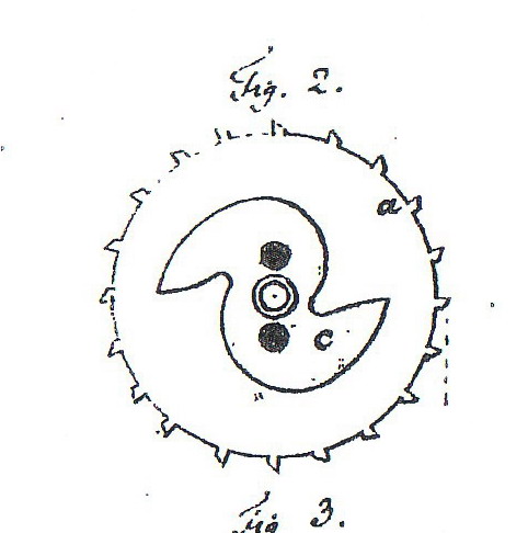
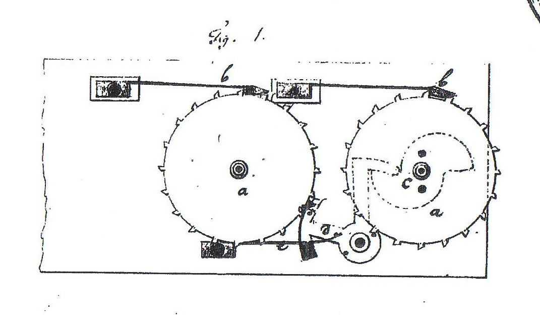
A) "Moving tooth" carry mechanism
Under the bonnet, it's relatively simple. For each axis there are, in superposed layers tightly connected to each other, a disc, a dial, a large gear wheel with 50 teeth and another, smaller and star shaped, with 10 teeth. This latter is held by a clamp armed with a spring (the jumper) which moves the wheel one tenth of a turn. This system serves as a ratchet and prevents the wheel going backwards.
Between each axis are so-called communication wheels. They allow the dials to turn in the same direction. But that's not all; each of them has a moving tooth which is part of the carry mechanism. Each time a wheel (for example the units wheel) makes a complete turn (passing from 0 to 9), the moving tooth makes the next wheel (in this case, the tens) advance by a tenth of a turn, etc…..
But why are these teeth moving? Roth insists on this.
Quite simply for a matter of independence. If, for example, one wants to add 900 to 797, one would enter the 9 on the hundreds wheel. This operation would have no effect on the tens or the units.
|
"Moving tooth" mechanism
(Mod-R1-A) |
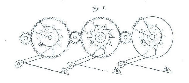
B) "Moving rack" carry mechanism
The communication wheels are replaced by small pinions and the moving tooth by a small rack, also moving, but situated this time on the dial wheel and equivalent to one tenth of it. In order that the rack can engage with the next higher decimal wheel, via the communication pinion, our inventor placed a small pin under the dial wheel. On the other hand, the spring gives it movement so that it doesn't affect the lower decimal orders.
|
Moving rack mechanism
(Mod-R1-B) |
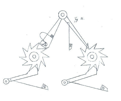
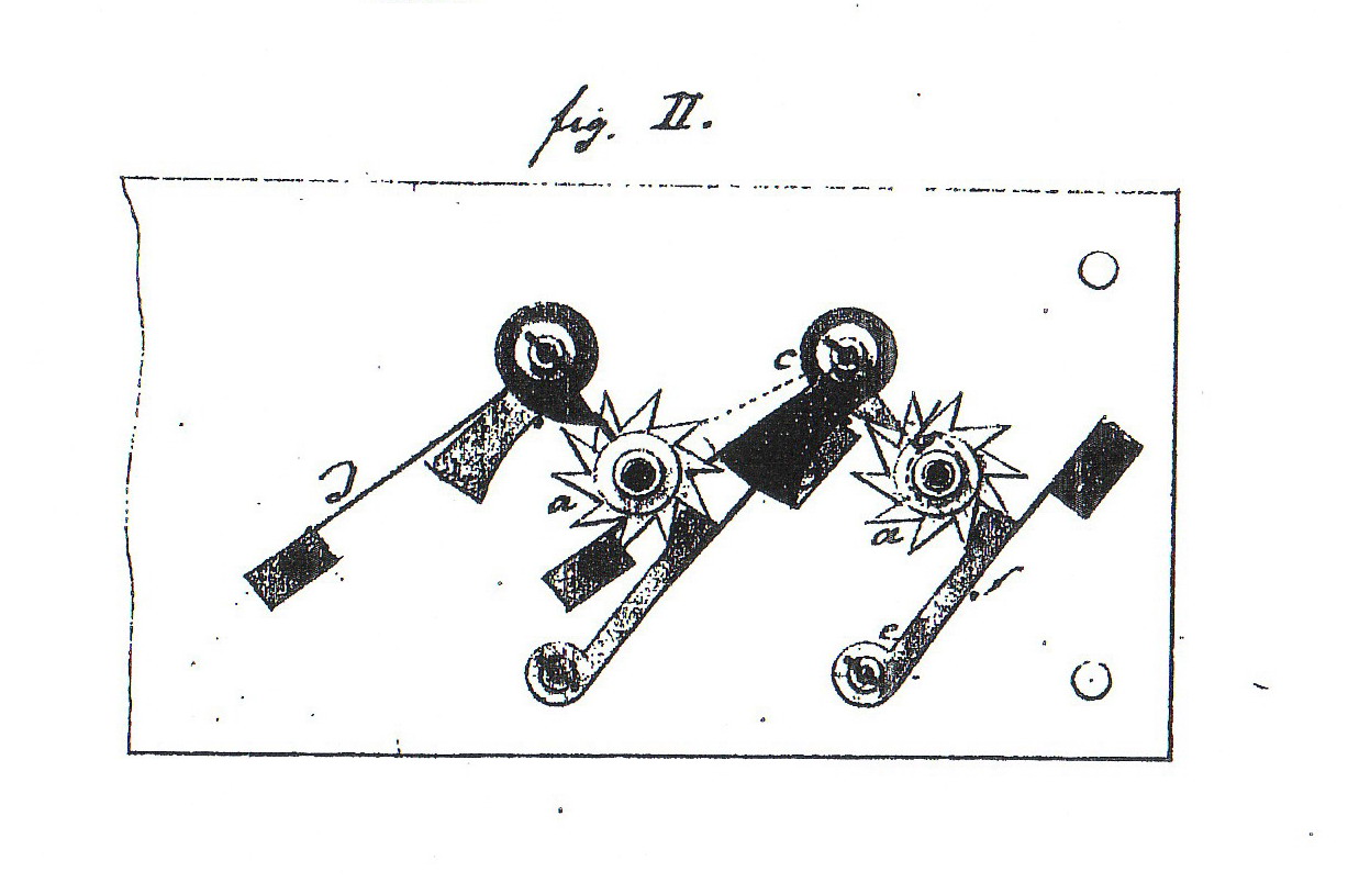
C) Lifting piece and mobile tooth
"The gear wheels are eliminated, only the star wheels remain, armed with a pin on one of their teeth. The communication is established by a lifting piece mounted on a spindle and a mobile tooth with its pin and spring." Roth, 1840
|
"Lifting piece + moving tooth" mechanism
(Mod-R1-C) |
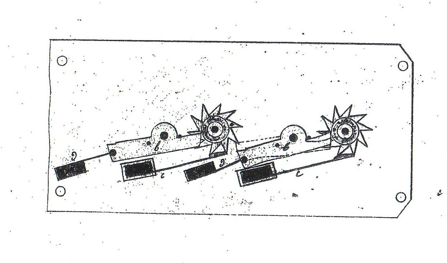
D) Ratchet mechanism
We have here "a ratchet wheel and a star wheel fixed below. On the shaft, a moving gear wheel, with its spring and ratchet, placed between the ratchet wheel and the star wheel, produces the same effect. A pinion can serve as communication. A small rack is fixed on the ratchet wheel. The pinion can be replaced by a wheel with a small rack attached to it. The whole acts as in the preceding case, above and below alternately" Roth, 1840
|
Ratchet mechanism
(Mod-R1-D) |
"One sets all the dials to 0 by placing the stylus in the hole corresponding to the small arrow on the disc and moving it from right to left until one feels it stopped by the hook.
To add, one locates the figure shown on the discs; then one puts the stylus in the corresponding hole and turns the disc until it is stopped by the hook. One repeats the procedure for all the figures one has to add, working from left to right or from right to left as desired but always taking care to add units to units, tens to tens, etc. The total is given by the figures that appear in the upper window and the addition therefore requires no mental work at all.
To subtract, one sets the dials to zero. The number from which one is subtracting corresponds to the numbers on the discs and the number one is subtracting to those on the circles. The remainder appears in the lower window of the plate." Roth, 1840
| III) Addition N° 1 to the patent |
A) Second attempt
The plates, discs, dials, figures and hooks are maintained. But the gear wheels and the communication wheels are eliminated. The clamp with its spring is retained.
Each axis contains only one star wheel armed with a finger which acts on a lever. During the carry process, the lever will push the following wheel by one notch.
|
"Second attempt"
(Mod-R2) |
B) Third attempt
The plates, discs, dials, figures and hooks are maintained. The fingers on the star wheels are eliminated which allows them all to be on the same level. A small rod, fixed perpendicularly on each wheel acts like a finger on an upright lever, reset by a spring. The clamps and springs have been removed, replaced by jumpers.
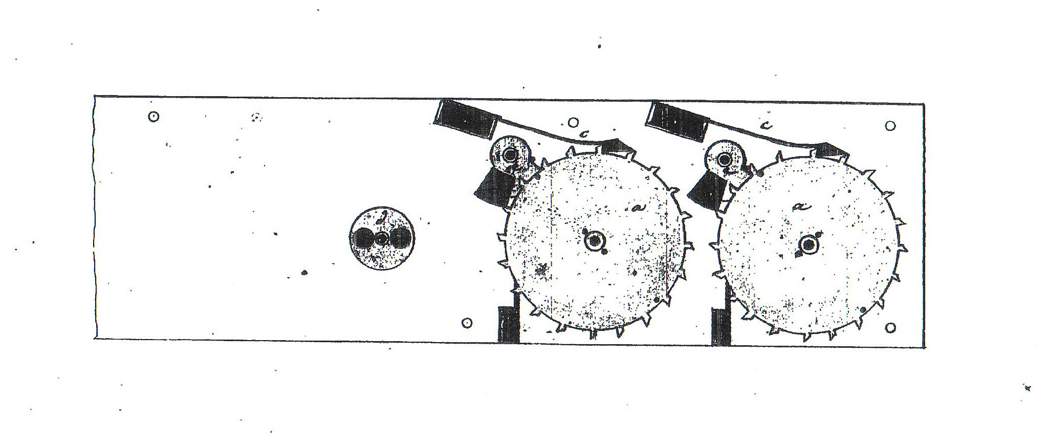
C) Fourth attempt
The dials have been suppressed. Now there is a series of wheels with twenty teeth on which are engraved two series of numbers in double (complemetary numbering). As each tooth corresponds to a unit, there's no longer one but two rods, fixed under the wheel which, on each half turn (0-9), act on a simplified lever which makes the following wheel advance by one notch. The inscription is still on the central disc pierced by its ten holes. It should be noted that the twenty teeth of the wheels are still not visible!! As is the case in subsequent models. The jumpers are maintained but placed in the opposite direction. The number of plates changes from 3 to 2.
|
"Fourth attempt"
(Mod-R4) |
D) Fifth attempt
The jumpers have gone. The lever now fulfills a double function. It serves as a stop jumper and also continues to act as a means of communication in the carry process. It seems that the toothed wheels are now armed with two small hooks instead of small rods. On each movement from 9 to 0, the hook acts on the lever a little like a balance, which makes the left hand wheel of a unit advance smoothly.
E) Sixth attempt
Roth has removed the figures which were engraved on the upper plate. Around each disc, he's opened ten windows beneath which the circular rings are arranged. According to the inventor, this method was developed on a machine of type A3, which leads one to suppose that dials, themselves placed on toothed wheels, are arranged under the rings,
The following, overlapping series of figures is inscribed on the rings: 1.8.2.7.3.6.4.5.5.4.6.3.7.2.8.1.9.0.
The rings are moved simultaneously by a rod fitted with a knob. Depending on whether one pulls the knob or not, the following numbers appear in the windows 1.2.3.4.5.6.7.8.9 or their complements 9.8.7.6.5.4.3.2.1. Under the tenth window (the results window), the rings have been partially cut so that the numbers on the dials appear. There are now 3 plates again.
|
Sixth attempt"
(Mod-R6) |
|
Detail of the prototype R6 of 1840-41
Source : CNAM |
F) Seventh attempt
Faced with the difficulty of making the rings described in the preceding attempt work, Roth imagined physically separating the figures 0.1.2.3.4.5.6.7.8.9 (addition) from their complement 9.8.7.6.5.4.3.2.1 (subtraction) by doubling up the discs and dials on the same plate. The rest of the mechanism (jumpers, levers) would not be doubled. It is adapted only on the higher series of numbers used for addition. Since the dials are toothed, they engage directly with those destined for subtraction giving them an opposite movement. To get the result of the addition or the subtraction, one pulls a metal band with the help of a rod and this serves as a cover.
(Note: two plates)
|
"Seventh attempt"
(Mod-R7) |
|
Prototype R7 of 1840-41
Source : CNAM |
G) Eighth attempt
Attempt not illustrated but described. This system works only on models R4-R5 which have wheels with twenty teeth. The discs are pierced with 20 holes as against 10 normally). The half on the right are used for addition and the left for subtraction. The series of numbers are placed semi-circularly and are red for subtraction. One finds this principle again on Roth's circular multiplier. Its outer circle is composed of 8 dials based on the same principle. (cf description of Roth's multiplier).
|
"Eight attempt"
who can be see partly on the circular machine
(Mod-R8) |
H) Ninth attempt
The plate has semi-circular slots through which one can see the teeth of the mechanism described in the 4th and 5th attempts (twenty toothed wheel). The figures are placed along this slot. One places the stylus directly between the teeth of the dial wheel at the point corresponding to the figure on which one wishes to operate.
The result appears in the upper openings provided for this. Depending on whether one is trying to make an addition or a subtraction, one pulls a rod fitted with a knob which moves the metal band which hides the unrequired part of the dial numbers.
I) Tenth attempt (not described)
This adder, dated January 1841, and kept in the CNAM collections, is not clearly identifiable. Only an examination of its mechanism allows one to situate it precisely. It resembles the prototype R1 of 1840 but does not have the complementary numbering on the dials. It could be a variant of type R2, R3, R4, R5 or R7 but, in any case, it is not capable of subtraction.
|
"Tenth attempt"(not described)
(Mod-R10) |
| IV) Addition N° 2 to the patent |
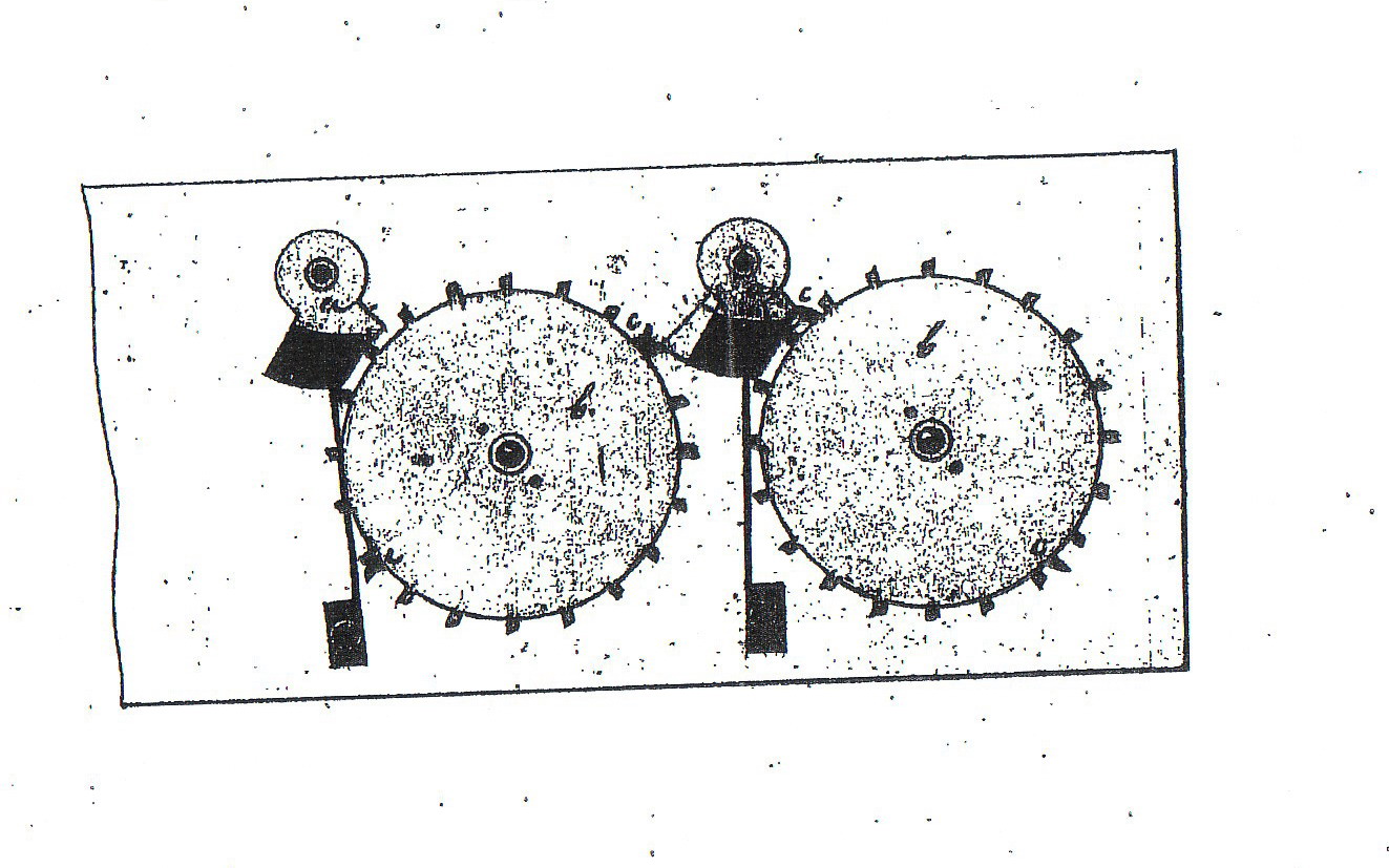
It's there that Roth's famous phrase takes on its full sense ("Feu de file"). One sees a clear improvement in the carry mechanism. The transmission of the carryto the higher orders of decimals is now carried out sequentially. As a result, the mechanical force required is always the same regardless of the number of figures.
This feat has been achieved thanks to the addition of a double cam (snail) under each wheel. In turning, this progressively winds up an elbowed lever stretched by a spring. This is suddenly released on passing ten and moves the following wheel by one notch (= one unit). The jumper springs are retained but are placed successively above and below for reasons of convenience. We do not have details of the plate but it seems that this system was adapted on plates of type R9.
According to the inventor, this system is also adaptable to perpendicular wheels which then have the figures on their edges. Did Roth build a uniaxial type of calculating machine?
|
|
The double cam |
Detail of the mechanism R10 |
*English version
by Eric Schurmann, November 2008*
|